
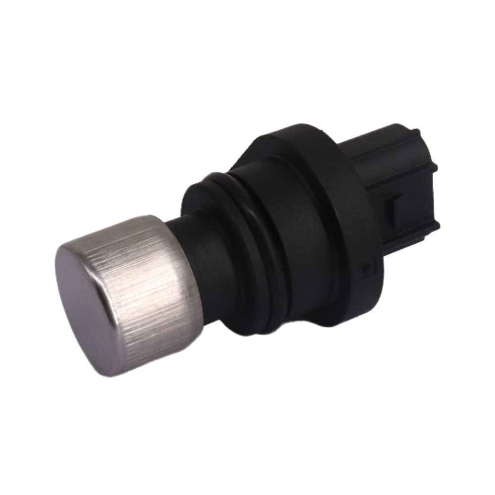
Modern motorcycles rely heavily on precise engine management systems to deliver optimal performance, fuel efficiency, and emissions control. At the heart of these sophisticated systems lies the motorcycle crankshaft sensor, a critical component that monitors crankshaft position and rotational speed. This small yet vital sensor provides essential data to the engine control unit, enabling precise timing for fuel injection, ignition, and valve operations. Understanding proper adjustment and optimization techniques for this sensor can significantly impact your motorcycle's overall performance and reliability.
Understanding Crankshaft Sensor Fundamentals
Sensor Operation Principles
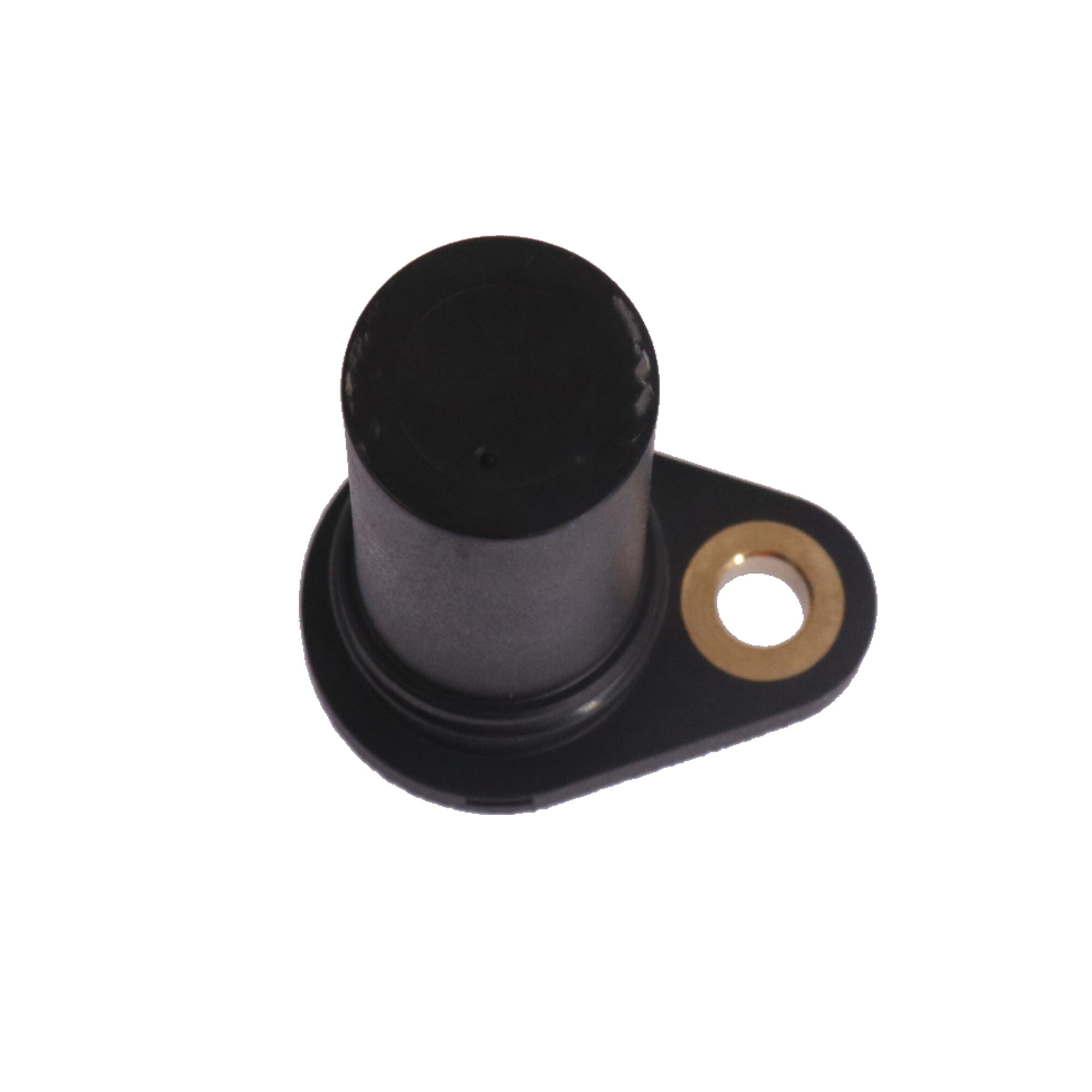
The crankshaft position sensor operates on electromagnetic induction principles, detecting the passage of teeth or notches on a reluctor wheel attached to the crankshaft. As the crankshaft rotates, the sensor generates electrical pulses corresponding to specific crankshaft positions. These signals are transmitted to the engine control module, which uses this information to calculate engine speed, determine piston positions, and coordinate various engine functions. The sensor's accuracy directly affects ignition timing, fuel delivery precision, and overall engine performance characteristics.
Most modern motorcycles utilize either Hall effect sensors or variable reluctance sensors for crankshaft position detection. Hall effect sensors require a power supply and produce digital square wave signals, while variable reluctance sensors generate analog sine wave signals without external power requirements. Each type has specific installation and adjustment procedures that must be followed to ensure optimal performance and longevity.
Signal Processing and ECU Integration
The engine control unit processes crankshaft sensor signals through sophisticated algorithms that filter noise, validate signal integrity, and calculate precise timing parameters. Signal quality depends on proper sensor positioning, clean electrical connections, and adequate gap spacing between the sensor and reluctor wheel. Poor signal quality can result in erratic engine operation, misfiring, or complete engine failure to start.
Advanced motorcycle engines often employ multiple crankshaft sensors or combine crankshaft and camshaft position sensors to achieve higher precision timing control. These systems require careful synchronization during installation and adjustment procedures to prevent timing conflicts that could damage engine components or reduce performance.
Diagnostic Procedures and Testing Methods
Visual Inspection Techniques
Before attempting any adjustments, thorough visual inspection of the crankshaft sensor assembly is essential. Examine the sensor housing for cracks, corrosion, or physical damage that could affect signal generation. Check the electrical connector for bent pins, corrosion, or loose connections that might cause intermittent signal loss. Inspect the reluctor wheel or trigger wheel for missing teeth, damage, or debris accumulation that could interfere with proper sensor operation.
Pay particular attention to the sensor mounting bracket and fastening hardware, as vibration can cause loosening over time. Ensure that all mounting surfaces are clean and free from oil, dirt, or corrosion that might affect sensor positioning accuracy. Document any visible damage or wear patterns that could indicate underlying mechanical issues requiring attention before sensor adjustment.
Electronic Testing Protocols
Electronic testing of the motorcycle crankshaft sensor requires appropriate diagnostic equipment, including digital multimeters, oscilloscopes, or specialized motorcycle diagnostic scanners. Begin by measuring sensor resistance values according to manufacturer specifications, typically ranging from 200 to 2000 ohms depending on sensor type and design. Compare measured values against service manual specifications to identify potential sensor degradation.
Signal pattern analysis using an oscilloscope provides valuable insights into sensor performance quality. Observe signal amplitude, frequency consistency, and waveform shape during engine cranking and various operating speeds. Irregular patterns, excessive noise, or amplitude variations may indicate sensor wear, improper gap adjustment, or electrical interference requiring corrective action.
Gap Adjustment and Positioning Techniques
Measuring and Setting Proper Air Gap
Precise air gap measurement between the sensor and reluctor wheel is crucial for optimal signal generation. Most motorcycle crankshaft sensors require gaps between 0.5mm and 2.0mm, with specific values detailed in the service manual. Use feeler gauges or specialized gap measurement tools to achieve accurate spacing. Insufficient gap may cause sensor damage from contact with the reluctor wheel, while excessive gap results in weak signals and poor engine performance.
During gap adjustment, ensure the crankshaft is positioned to place the reluctor wheel teeth at their closest approach to the sensor. Loosen sensor mounting bolts and carefully adjust position while monitoring gap measurement. Some sensors utilize slotted mounting holes allowing fine adjustment, while others require shimming or bracket modification to achieve proper spacing.
Alignment and Mounting Considerations
Proper sensor alignment ensures consistent gap spacing across the entire reluctor wheel circumference. Misalignment can cause gap variations that result in irregular signal patterns and timing inconsistencies. Use dial indicators or specialized alignment tools to verify sensor perpendicularity to the reluctor wheel surface. Adjust mounting bracket position or add shims as necessary to achieve proper alignment.
Secure all mounting hardware to specified torque values using thread locking compounds where recommended. Verify that sensor positioning remains stable during engine operation by checking gap measurements after initial test running. Vibration and thermal cycling can affect mounting stability, particularly in high-performance applications requiring periodic verification.
Calibration and Synchronization Procedures
ECU Learning and Adaptation
After completing physical sensor adjustments, the engine control unit may require calibration procedures to adapt to the new sensor positioning. Many modern motorcycles feature automatic learning algorithms that adjust timing parameters based on sensor signal characteristics. Allow the engine to complete several warm-up and cool-down cycles while monitoring for proper operation and absence of diagnostic trouble codes.
Some systems require manual calibration procedures using diagnostic equipment to establish baseline timing references. Follow manufacturer-specific procedures for timing light verification, idle speed adjustment, and throttle position sensor synchronization. Document all calibration values for future reference and troubleshooting purposes.
Performance Validation Testing
Comprehensive performance testing validates the effectiveness of sensor adjustment and calibration procedures. Monitor engine operation across various speed and load conditions, paying attention to smooth acceleration, consistent idle quality, and absence of hesitation or misfiring. Use diagnostic scanners to observe real-time sensor data and verify signal quality meets manufacturer specifications.
Road testing under normal operating conditions provides final validation of sensor optimization effectiveness. Monitor fuel economy, throttle response, and overall drivability improvements resulting from proper sensor adjustment. Document performance baseline data for comparison during future maintenance intervals.
Common Issues and Troubleshooting Solutions
Signal Interference and Noise Reduction
Electromagnetic interference from ignition systems, charging circuits, or aftermarket electrical accessories can compromise crankshaft sensor signal quality. Install ferrite cores on sensor wiring, ensure proper grounding of electrical components, and route sensor cables away from high-current circuits. Use shielded cables where specified and maintain proper separation distances from potential interference sources.
Environmental factors such as moisture, oil contamination, or temperature extremes can affect sensor performance. Apply appropriate sealants to electrical connections, ensure proper drainage of sensor mounting areas, and verify that environmental protection measures remain effective throughout the service interval.
Mechanical Wear and Degradation
Reluctor wheel wear, sensor housing deterioration, or mounting system loosening can gradually degrade performance over time. Implement regular inspection schedules to identify wear patterns before they affect engine operation. Replace worn components proactively rather than waiting for complete failure that could result in engine damage or safety hazards.
Establish maintenance records tracking sensor performance metrics, adjustment history, and replacement intervals. This data helps predict future maintenance requirements and identifies recurring issues that might indicate underlying design limitations or operational factors requiring attention.
Advanced Optimization Strategies
Performance Enhancement Modifications
High-performance motorcycle applications may benefit from upgraded motorcycle crankshaft sensor systems offering improved accuracy, faster response times, or enhanced durability. Consider sensors with higher resolution reluctor wheels, improved signal processing capabilities, or ruggedized construction for racing or extreme operating conditions.
Aftermarket engine management systems often require sensor modifications or replacements to achieve optimal compatibility. Research compatibility requirements, signal format specifications, and calibration procedures before implementing modifications that could affect warranty coverage or regulatory compliance.
Predictive Maintenance Implementation
Modern diagnostic capabilities enable predictive maintenance approaches that identify sensor degradation trends before performance impacts become apparent. Monitor signal quality metrics, response time measurements, and error rate statistics to establish baseline performance characteristics. Set alert thresholds that trigger maintenance actions before complete sensor failure occurs.
Integrate sensor monitoring into comprehensive motorcycle maintenance programs that consider operating environment, usage patterns, and performance requirements. This proactive approach minimizes unexpected failures while optimizing maintenance costs and ensuring consistent performance throughout the service life.
FAQ
How often should motorcycle crankshaft sensors be inspected and adjusted
Crankshaft sensors should be inspected during regular maintenance intervals, typically every 12,000 to 15,000 miles or annually, whichever comes first. However, high-performance motorcycles or those operated in harsh conditions may require more frequent inspection every 6,000 to 8,000 miles. Signs requiring immediate attention include rough idle, poor acceleration, or diagnostic trouble codes related to crankshaft position sensing.
What tools are required for proper crankshaft sensor gap adjustment
Essential tools include feeler gauges ranging from 0.5mm to 2.0mm, a digital multimeter for resistance testing, basic hand tools for sensor removal and installation, and an oscilloscope or diagnostic scanner for signal verification. Some applications may require specialized gap measurement tools or alignment fixtures specified by the manufacturer for precise adjustment procedures.
Can incorrect sensor gap adjustment cause engine damage
Yes, improper gap adjustment can cause significant engine damage. Insufficient gap may result in physical contact between the sensor and reluctor wheel, damaging both components and potentially causing metal debris to contaminate the engine oil. Excessive gap creates weak signals leading to timing errors, misfiring, and potential valve or piston damage from incorrect combustion timing.
What are the symptoms of a failing or improperly adjusted crankshaft sensor
Common symptoms include difficulty starting, intermittent stalling, rough idle, poor acceleration, reduced fuel economy, and illuminated check engine lights. Advanced cases may exhibit complete failure to start, erratic tachometer readings, or engine shutdown during operation. Diagnostic scanners typically display specific trouble codes related to crankshaft position sensor circuit malfunctions or signal quality issues.