
 EN
EN
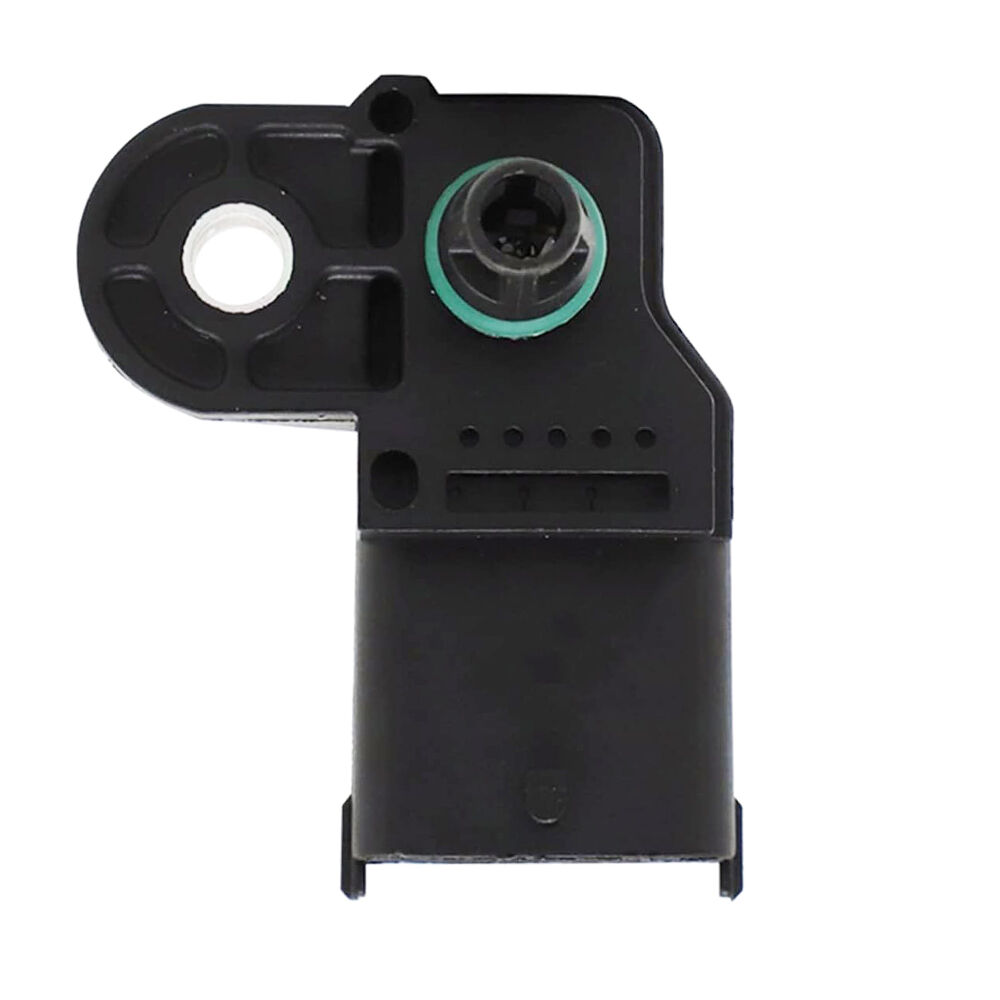
A map sensor is one of the most critical components in a fuel-injected engine management system, responsible for measuring the absolute pressure inside the intake manifold and relaying that data to the engine control unit. When this sensor is functioning correctly, the ECU can calculate the precise air mass entering the engine and adjust fuel delivery and ignition timing accordingly. Even small deviations in map sensor readings can cascade into rough idling, poor fuel economy, sluggish throttle response, and increased emissions — problems that become harder to diagnose the longer they go unaddressed.
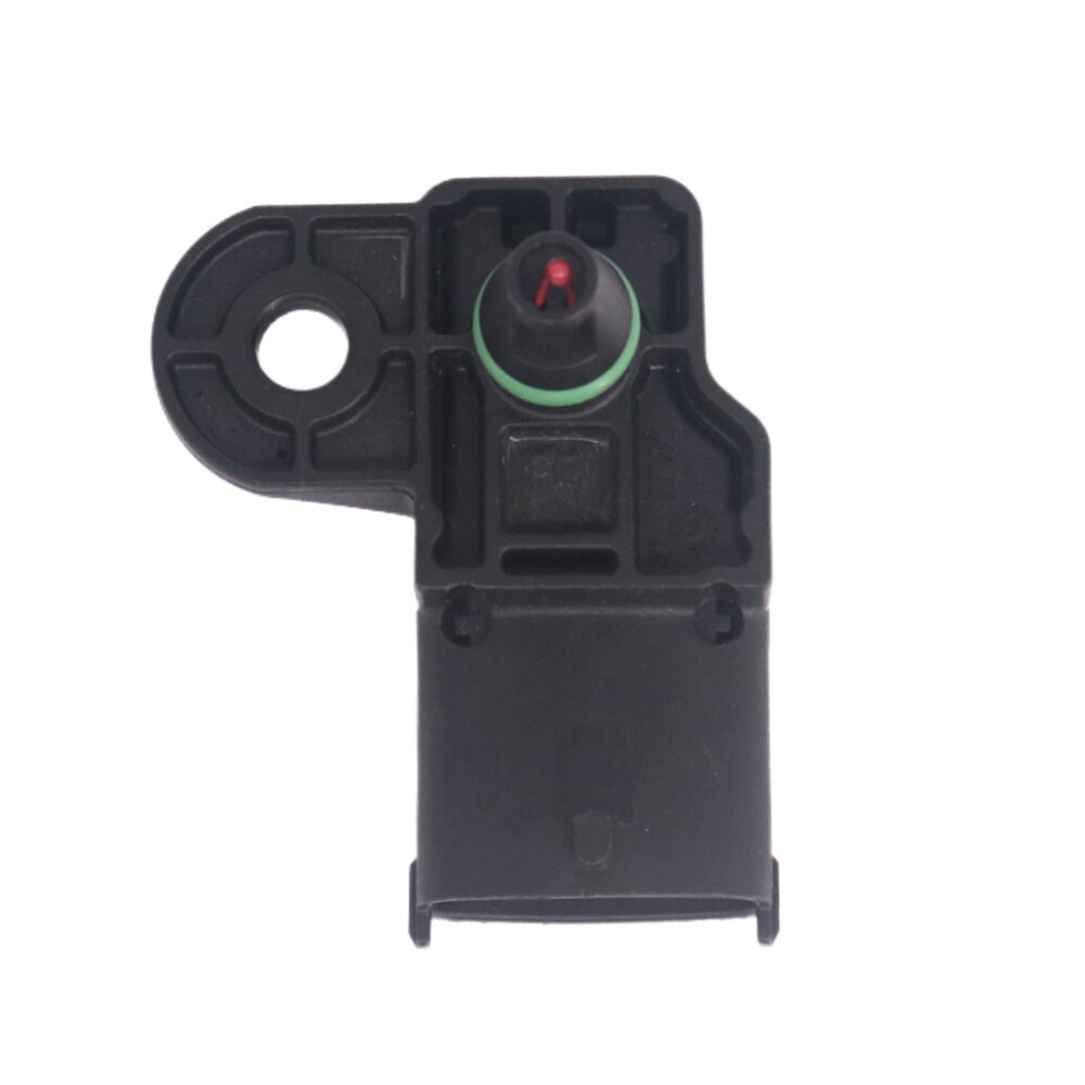
Maintaining a map sensor for long-term consistent readings is not merely a reactive task performed when something goes wrong. It is a proactive discipline that combines correct installation practices, periodic cleaning, environmental protection, circuit integrity checks, and timely replacement decisions. This article walks through every meaningful step of that process, offering practical guidance for mechanics, fleet technicians, and anyone responsible for keeping fuel-injected engines performing at their best over extended service periods.
Understanding What Affects Map Sensor Accuracy Over Time
Physical Contamination Inside the Pressure Port
The map sensor relies on a small pressure port that connects directly to the intake manifold. Over time, oil vapor, carbon particles, and moisture from blow-by gases can enter this port and coat the sensing element or partially obstruct the passage. When contamination builds up, the sensor cannot respond accurately to real-time pressure changes, and the readings it delivers to the ECU gradually drift from their true values.
This type of contamination is particularly common in high-mileage engines that consume small amounts of oil or in engines where the PCV system is not functioning optimally. Engines used in dusty or humid environments are also more prone to port contamination. Recognizing contamination as a primary cause of long-term drift is the first step toward developing a maintenance routine that actually addresses root causes rather than symptoms.
Performing visual inspections of the pressure port at every major service interval allows technicians to catch early-stage contamination before it becomes severe enough to cause drivability issues. A thin film of oily residue around the port opening is an early warning sign that more thorough cleaning is warranted.
Electrical and Signal Degradation
Beyond physical contamination, the electrical side of the map sensor is equally vulnerable to degradation. The sensor typically operates on a five-volt reference signal from the ECU and returns an analog voltage proportional to manifold pressure. Corrosion on connector pins, damaged shielding on signal wires, or high-resistance ground connections can all introduce noise or offset errors into the output signal.
Vibration is another factor that weakens electrical connections over time. In motorcycle applications especially, constant engine and road vibration gradually loosens connector locking tabs and causes micro-abrasion on wire insulation near attachment points. These small but cumulative changes can cause the map sensor signal to become erratic rather than exhibiting a clean, predictable voltage sweep.
Understanding that both mechanical and electrical degradation occur simultaneously helps technicians design a maintenance schedule that addresses both dimensions rather than focusing exclusively on the sensor element itself.
Step-by-Step Cleaning and Inspection Procedure
Preparing for Safe Sensor Removal
Before removing a map sensor for cleaning or inspection, allow the engine to cool completely and disconnect the negative battery terminal to eliminate the risk of triggering fault codes or damaging the ECU during the process. Label or photograph the wiring harness routing before disconnecting the connector, since reinstalling connectors in the wrong orientation can introduce ground loops or pin damage.
Use a gentle rocking motion when releasing the electrical connector rather than pulling sharply on the wiring. Many map sensor connectors use a squeeze-tab or slide-lock retention mechanism, and forcing them causes the plastic to crack, leading to loose connections that undermine signal integrity after reinstallation. Having the correct removal tool for the specific connector type is worth the small investment.
Once the connector is safely disconnected, unbolt or unclip the sensor body from the intake manifold. Note the orientation of any sealing O-ring, since a twisted or misaligned O-ring on reinstallation can allow unmetered air into the manifold, which will itself produce inaccurate readings from the map sensor even after cleaning.
Cleaning the Sensor Element and Port
Use only electronics-safe sensor cleaner or mass airflow sensor cleaner sprays for cleaning a map sensor. These products evaporate completely without leaving residue and are formulated to avoid damaging sensitive piezoelectric or piezoresistive sensing elements. Do not use carb cleaner, brake cleaner, or compressed air directly into the sensing cavity, as all of these can permanently damage the delicate diaphragm or contaminate it further.
Hold the sensor with the pressure port facing downward and apply the cleaner in short bursts, allowing gravity to carry dissolved contamination out of the port opening rather than pushing it deeper. Repeat this process two or three times and allow the sensor to air-dry completely on a clean lint-free cloth before reinstallation. Never use cotton swabs or brushes inside the pressure port, as fibers and bristles can lodge against the sensing element.
Inspect the O-ring or gasket sealing surface on both the sensor body and the manifold port. A hardened, cracked, or flattened O-ring should be replaced rather than reused. A compromised seal directly undermines everything the map sensor is trying to measure by allowing false air leakage that the sensor cannot distinguish from actual manifold pressure variations.
Protecting the Map Sensor in Demanding Operating Environments
Heat and Vibration Management
The map sensor is typically mounted close to the intake manifold, which means it experiences significant thermal cycling every time the engine is started and shut down. Over thousands of cycles, thermal expansion and contraction gradually stress the solder joints inside the sensor housing and can cause hairline fractures in the ceramic substrate that supports the sensing element. While this type of failure is rare in quality sensors, it becomes more likely when sensors are exposed to temperatures consistently above their rated operating range.
Ensuring that intake heat shields and engine bay insulation are intact and correctly fitted helps limit the thermal load on the map sensor. In high-performance or modified engines where intake temperatures are elevated compared to stock configurations, verifying that the replacement map sensor carries an appropriate temperature rating for the application is an important pre-installation step.
Vibration management involves checking that the sensor mounting bracket or boss is not cracked or loose, since even small amounts of play allow the sensor to vibrate independently of the manifold, fatiguing the wiring harness at the connector entry point and eventually causing intermittent open circuits.
Moisture and Contaminant Exclusion
Moisture is particularly damaging to map sensor electrical connections. In vehicles or motorcycles used in wet climates or washed regularly with high-pressure water, moisture intrusion into connectors causes galvanic corrosion on the copper pin surfaces. This corrosion increases contact resistance, which shifts the sensor output voltage even when manifold pressure is stable, producing what appears to the ECU as an unexpected change in engine load.
Applying a small amount of dielectric grease to the electrical connector pins before closing the connector provides a moisture-excluding barrier without impeding electrical conductivity. This practice is inexpensive and significantly extends the service life of the sensor's electrical interface. Reapply the grease each time the connector is opened during maintenance.
For vehicles stored outdoors or in humid climates, inspecting the entire wiring harness section near the map sensor at least once annually and replacing any sections showing green patina or white crystalline deposits on the outer insulation is a worthwhile preventive measure.
Diagnosing Early Signs of Map Sensor Drift
Using Live Data to Catch Problems Before They Worsen
Modern diagnostic scan tools allow technicians to observe live map sensor voltage or pressure values while the engine is running. A healthy map sensor at idle should display a stable, consistent pressure reading in the range specified by the engine manufacturer, typically somewhere between 25 and 45 kPa for naturally aspirated engines at idle. Readings that fluctuate randomly, spike unexpectedly, or remain frozen at a fixed value all point to sensor problems that warrant immediate attention.
Comparing the map sensor reading at idle to the barometric pressure reading — which many ECUs store as a reference at key-on before starting — provides a quick sanity check. If the difference between barometric and manifold pressure at idle is outside the expected range for the engine's vacuum characteristics, contamination or sensor drift is a likely culprit. This test requires no special equipment beyond a scan tool with live data capability.
Snap-throttle tests using live data reveal whether the map sensor responds quickly and proportionally to rapid load changes. A slow or non-linear response during a snap-throttle indicates a partially obstructed pressure port, a damaged sensing element, or a slow response caused by condensation inside the port cavity.
Recognizing Symptom Patterns That Point to the Map Sensor
Rich running conditions at idle combined with lean conditions under load — or the reverse — are classic symptoms of a map sensor that is reading incorrectly across different pressure ranges. Because the sensor's output is used across the entire operating range of the engine, a fault that only affects one portion of its pressure range can produce apparently contradictory symptom patterns that are easy to misattribute to injectors, fuel pressure, or lambda sensors.
Fuel trim data from the ECU is particularly useful for detecting map sensor drift. High positive long-term fuel trims at idle with relatively normal trims at high load suggest the sensor is over-reporting vacuum at idle, causing the ECU to command a leaner mixture that the fuel trims then compensate for. Cross-referencing fuel trim data with live map sensor readings is one of the most efficient ways to determine whether the sensor needs cleaning, recalibration, or replacement.
Storing diagnostic freeze frame data when fault codes appear makes it easier to analyze conditions that triggered the code, which in turn helps separate genuine map sensor faults from transient events caused by vacuum leaks elsewhere in the intake system.
When Cleaning Is Not Enough: Replacement Decision Criteria
Recognizing Irreversible Sensor Degradation
Not all map sensor problems can be resolved through cleaning and maintenance. When the sensing element itself is damaged — whether through impact, chemical contamination from inappropriate cleaners, or end-of-life diaphragm fatigue — the sensor must be replaced. One reliable indicator of irreversible damage is a sensor that continues to produce erratic or offset readings even after thorough cleaning and after all wiring connections have been verified as sound.
Another clear replacement indicator is a map sensor that passes bench inspection and initial reinstallation but begins producing inconsistent readings again within a short period of operation. Rapid recontamination can indicate an underlying engine condition such as excessive blow-by or a failed PCV valve, but it can also mean the sensor's internal sealing has been compromised and it is no longer able to exclude contaminants effectively.
When selecting a replacement map sensor, choosing a component designed and calibrated for the specific engine application ensures that the voltage output curve matches what the ECU expects across the full pressure range. A map sensor calibrated for a different displacement or boost range may produce plausible-looking readings at idle but introduce significant errors under load, making the replacement harder to diagnose than the original fault.
Establishing a Proactive Replacement Interval
For fleet operators and maintenance managers responsible for multiple vehicles, establishing a proactive replacement interval for the map sensor as part of a scheduled maintenance program reduces unplanned downtime and diagnostic labor costs. Rather than waiting for a sensor to fail outright, replacing it alongside other high-wear intake components at a defined mileage or hour interval ensures consistent engine management performance throughout the service period.
The appropriate interval depends on operating conditions. Engines in clean environments with well-maintained PCV systems may see map sensor service lives well beyond 100,000 km, while those in dusty, oily, or high-humidity environments may benefit from inspection and potential replacement at shorter intervals. Tracking diagnostic fault code history for map sensor-related codes across a fleet provides the data needed to calibrate a sensible replacement interval for a specific application.
Keeping a small inventory of correctly specified replacement map sensor units on hand eliminates wait times when an unexpected replacement is needed, which is especially valuable for commercial fleets where vehicle downtime directly translates to revenue loss.
FAQ
How often should a map sensor be cleaned during routine maintenance?
For most engines, inspecting and cleaning the map sensor every 30,000 to 50,000 km or during each major service interval is a reasonable baseline. Engines operating in dusty environments, high-humidity conditions, or with oil consumption issues should be inspected more frequently. If live data reveals drifting idle pressure readings at any service interval, cleaning should be performed immediately regardless of the scheduled interval.
Can a dirty map sensor cause a check engine light?
Yes. A map sensor that is providing out-of-range or irrational readings will trigger fault codes related to manifold pressure signals, and these codes will illuminate the check engine light. In some cases, the sensor may produce plausible but slightly offset readings that do not trigger a code immediately but cause gradual fuel trim adaptation, which eventually pushes fuel trims outside their acceptable range and triggers related fault codes. Regular maintenance helps prevent both types of faults.
Is it safe to clean a map sensor while it is still mounted on the engine?
Light cleaning of the exterior pressure port with sensor-safe cleaner spray is possible with the sensor in place, provided the engine is off and cool and the electrical connector is protected from the cleaner. However, for thorough cleaning and inspection of the O-ring and connector pins, removing the sensor from the manifold is strongly recommended. In-place cleaning without removal risks forcing contamination deeper into the port or allowing cleaner to contact the connector, which can corrode pin surfaces.
What is the difference between a map sensor and a MAF sensor in terms of maintenance needs?
Both sensors measure parameters related to air entering the engine, but they do so differently and face different contamination risks. A MAF sensor measures actual airflow using a hot-wire or hot-film element and is vulnerable to dust and fiber contamination on the sensing wire. A map sensor measures intake manifold pressure and is more susceptible to oil vapor and carbon contamination in the pressure port. Maintenance procedures for each are similar in principle — using appropriate sensor-safe cleaners and gentle techniques — but the specific locations and types of contamination to target differ between the two sensor types.