
 EN
EN
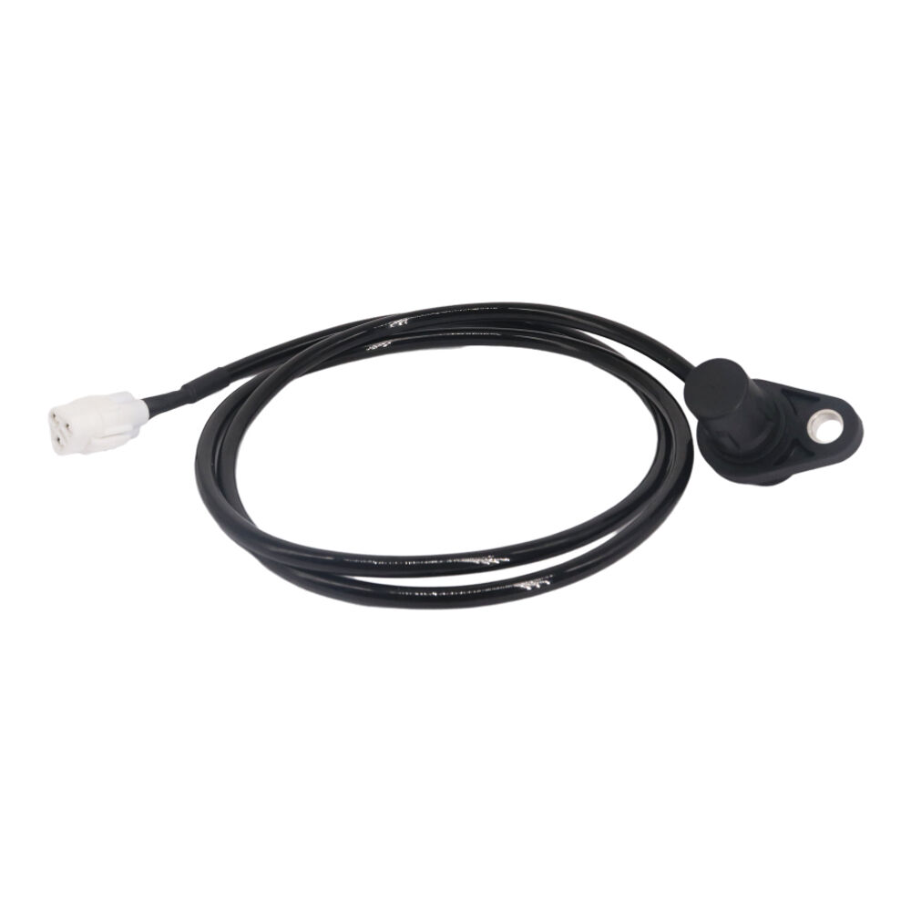
The speed sensor is one of the most quietly essential components in any modern transmission system, yet it rarely receives the attention it deserves until something goes wrong. Whether you are operating a motorcycle, a passenger car, or a commercial vehicle, the transmission's ability to shift gears smoothly and accurately is deeply dependent on real-time velocity data — data that only the speed sensor can reliably deliver. Without it, the transmission control unit would essentially be operating blind, making arbitrary shift decisions that could result in rough gear changes, poor fuel efficiency, and long-term mechanical wear.
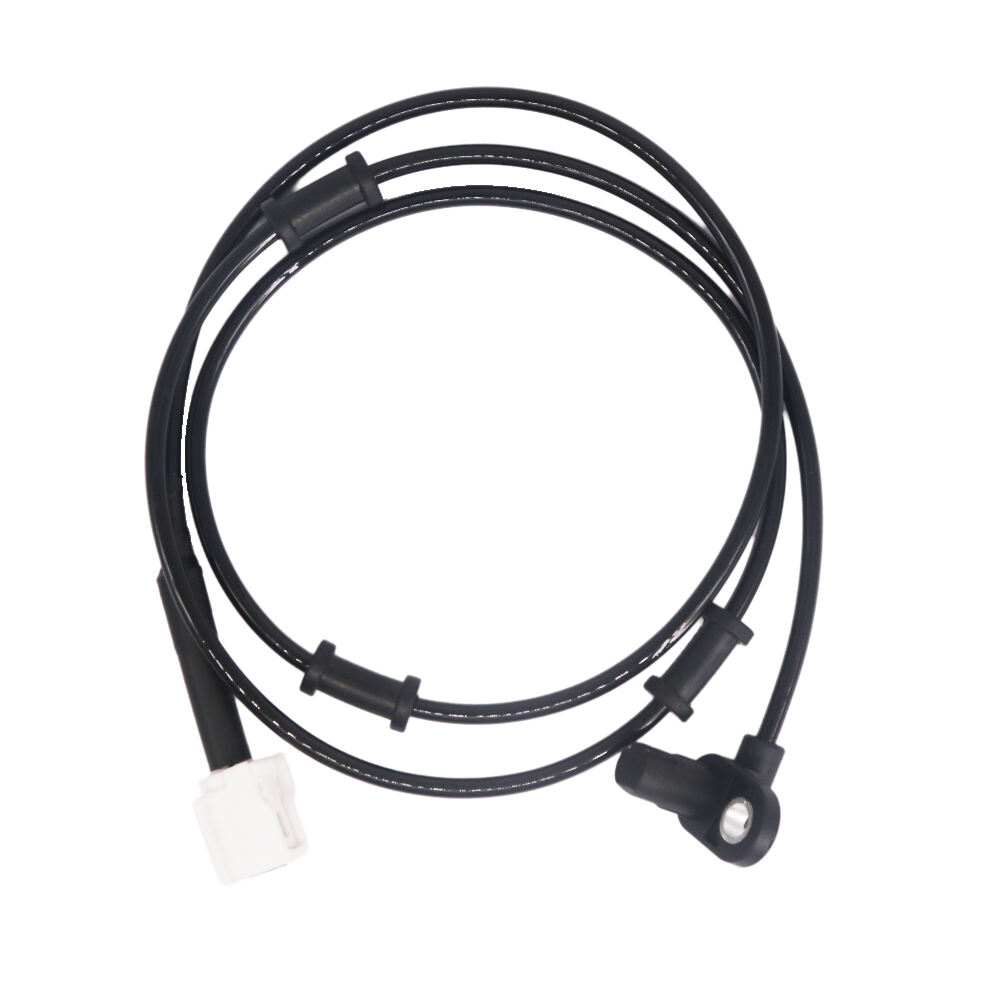
Understanding what the speed sensor actually does within the transmission shifting process is critical for technicians, vehicle owners, and procurement professionals alike. This article explores the specific functions of the speed sensor in governing shift behavior, the types used in modern drivetrains, how signal faults affect performance, and why maintaining sensor integrity is a non-negotiable part of drivetrain health management. From automatic transmissions on full-sized sedans to CVT and ABS-integrated systems on motorcycles like the Yamaha NMAX155, the speed sensor plays a central role that spans both safety and efficiency.
The Core Function of the Speed Sensor in Transmission Systems
How the Speed Sensor Communicates with the Transmission Control Unit
At its most fundamental level, the speed sensor generates an electrical signal that reflects rotational velocity — either of a wheel, an input shaft, or an output shaft within the drivetrain. This signal is transmitted continuously to the transmission control unit (TCU), which uses it as the primary input for determining when and how to shift gears. The TCU compares incoming speed data against a programmed shift map to execute gear changes at precisely the right moment, matching engine load and road speed for optimal performance.
In automatic transmissions, the speed sensor output directly triggers hydraulic valve activation, which in turn engages or disengages specific clutch packs and bands. The precision of this process depends entirely on the accuracy of the speed sensor signal. Even a slight delay or deviation in the signal can cause the TCU to misjudge the ideal shift point, leading to hard shifts, hunting between gears, or unexpected downshifts under steady throttle.
Modern vehicles often use multiple speed sensors — including both input and output shaft sensors — so that the TCU can calculate the actual gear ratio in use at any given moment. This dual-sensor configuration gives the system a layered level of awareness that single-sensor designs cannot match. The interplay between these sensors allows for far more nuanced shift scheduling across varied driving conditions.
Speed Sensor Role in Determining Shift Points
Shift points in an automatic or semi-automatic transmission are not fixed thresholds — they are dynamic values that change based on driving conditions, throttle position, engine load, and most importantly, vehicle speed. The speed sensor is the component that continuously supplies the velocity component of this calculation. Without accurate speed data, the TCU cannot correctly determine when upshifts or downshifts should occur.
For example, when a driver gradually accelerates from a stop, the speed sensor relays increasing rotational velocity data to the TCU, which uses that information to time each upshift as the engine approaches its optimal RPM band. If the speed sensor provides erratic or delayed data, the transmission may shift too early, causing the engine to lug, or too late, pushing the engine beyond its efficient operating range and causing unnecessary fuel consumption.
In performance-oriented transmission calibrations, the speed sensor data is also used to enable 'skip-shift' logic and sport shift modes, where the system holds gears longer to maximize power delivery. This level of precision depends on a speed sensor that provides clean, stable, and accurate output throughout the entire operating range of the vehicle.
Types of Speed Sensors Used in Transmission Applications
Magnetic and Hall-Effect Speed Sensor Designs
The two most widely used speed sensor technologies in transmission and drivetrain applications are the passive magnetic (variable reluctance) type and the active Hall-effect type. A passive magnetic speed sensor operates without an external power supply, generating voltage through electromagnetic induction as a toothed reluctor wheel rotates past the sensor tip. The signal amplitude varies with rotation speed, which means it becomes weaker at very low vehicle speeds — a known limitation of this design.
The Hall-effect speed sensor, by contrast, requires a power supply but produces a clean, consistent digital square wave signal across the full speed range, including at very low velocities. This makes it far better suited to modern transmission systems that must respond to precise shift commands even during slow crawling in traffic or during initial vehicle launch. The Hall-effect speed sensor is now the dominant type in newer vehicles and motorcycles due to its superior accuracy and signal consistency.
On motorcycles such as the Yamaha NMAX155, which integrates an ABS system with traction monitoring, the speed sensor is typically a Hall-effect unit mounted at the wheel hub or alongside the brake rotor. This placement allows the sensor to measure wheel speed directly, feeding accurate data simultaneously to the ABS controller and any transmission-related control logic present in the system.
Input Shaft vs. Output Shaft Speed Sensors
In many automatic transmissions, separate speed sensors are used for the input shaft and the output shaft. The input shaft speed sensor monitors the rotational speed of the shaft entering the transmission from the engine side, while the output shaft speed sensor measures speed on the exit side going toward the wheels. The ratio between these two readings tells the TCU which gear is currently engaged.
This is particularly valuable for detecting slipping clutch packs or torque converter issues. If the input shaft speed sensor shows one value while the output shaft speed sensor shows a value inconsistent with the expected gear ratio, the TCU flags this as a potential mechanical fault and may trigger a fault code or enter a limp-home mode to prevent further damage.
When either the input or output speed sensor fails, the TCU loses part of its positional awareness, often defaulting to a fixed gear or refusing to shift beyond a certain point. This is why diagnosing a shifting problem should always include testing the speed sensor signals before replacing more expensive transmission components.
How a Faulty Speed Sensor Disrupts Transmission Shifting
Symptoms of Speed Sensor Signal Failure
When a speed sensor begins to fail or delivers corrupted data, the effects on transmission behavior are often immediate and noticeable. The most common symptom is erratic or harsh shifting — the transmission may bang into gear unexpectedly or hesitate during gear changes that were previously smooth. Drivers may also notice the transmission slipping between gears or failing to engage a specific gear range at all.
Another frequent symptom is the illumination of the check engine light or a transmission warning indicator on the dashboard. The TCU logs diagnostic trouble codes related to the speed sensor circuit when it detects a signal that falls outside expected parameters. In some cases, the vehicle may enter a reduced-function 'limp mode,' which restricts the transmission to a single gear to prevent damage during continued operation.
In ABS-equipped motorcycles, a malfunctioning speed sensor at the wheel can also trigger the ABS warning light, since the same sensor often feeds both the braking system and the powertrain management system. This dual-use nature of the speed sensor means a single failing unit can affect multiple vehicle systems simultaneously, making prompt diagnosis and replacement critically important.
Diagnosing Speed Sensor Issues Before They Escalate
Diagnosing a faulty speed sensor typically begins with an OBD scan to retrieve any stored fault codes related to wheel or shaft speed circuits. Codes pointing to 'speed sensor circuit range/performance' or 'no signal' conditions are strong indicators that the sensor itself, its wiring harness, or the reluctor ring may be the root cause. Visual inspection of the sensor tip for debris, magnetic contamination, or physical damage should follow any code-based diagnosis.
An oscilloscope or digital multimeter can be used to verify that the speed sensor is producing the correct signal pattern when the wheel or shaft is rotated. A healthy speed sensor should produce a clean wave pattern with consistent amplitude and frequency. Irregular patterns, intermittent dropouts, or flat lines indicate sensor failure or wiring degradation that needs to be addressed immediately.
Replacing the speed sensor promptly after confirmed failure is always more cost-effective than allowing the TCU to continue operating on corrupted data. Extended use of a failing speed sensor can cause the TCU to make incorrect clutch engagement decisions, accelerating wear on already-stressed transmission components and leading to far more expensive repairs down the line.
Speed Sensor Maintenance and Replacement Considerations
Factors That Affect Speed Sensor Longevity
The operating environment of a speed sensor is harsh by design. Road grime, brake dust, temperature cycling, moisture ingress, and vibration all act to degrade sensor performance over time. In motorcycle applications where the speed sensor is mounted near the wheel or brake assembly, it is exposed to particularly severe contamination risks, especially during wet weather or off-road conditions. Regular inspection of the sensor tip and connector is therefore a worthwhile part of any maintenance schedule.
Connector corrosion is one of the leading causes of speed sensor signal degradation that does not show up as a hard fault on initial inspection. Even a small amount of oxidation at the connector pins can introduce resistance that distorts the sensor signal without fully interrupting it — creating intermittent faults that are notoriously difficult to reproduce during workshop diagnostics. Applying dielectric grease to connectors during any service that involves disconnecting the speed sensor is a simple preventive measure with meaningful long-term benefits.
The reluctor ring or tone wheel that the speed sensor reads also requires attention. If teeth on the ring become damaged, corroded, or packed with debris, the sensor will produce an incomplete signal regardless of its own condition. Cleaning the reluctor ring during brake service or suspension work is a low-cost step that extends the useful life of the speed sensor significantly.
Choosing the Right Replacement Speed Sensor
When sourcing a replacement speed sensor, it is essential to match the sensor's specifications precisely to the original equipment requirements. Signal type (analog vs. digital), connector configuration, operating voltage range, mounting thread, and gap tolerance must all align with what the TCU expects to receive. Installing a speed sensor with the wrong output signal type can confuse the TCU and produce symptoms similar to having no sensor at all.
For motorcycle applications such as the Yamaha NMAX155, the rear wheel speed sensor plays a direct role in both ABS function and overall speed-referenced control logic. Using an OEM-equivalent speed sensor ensures that signal characteristics match exactly what the ECU and ABS module were calibrated to interpret. Aftermarket sensors that meet or exceed OEM specifications are acceptable, provided they have been validated for compatibility with the specific model's control systems.
Procurement teams and workshop managers sourcing speed sensor replacements at scale should also consider packaging quality, storage conditions, and shelf life. A speed sensor that has been improperly stored — exposed to humidity or extreme temperatures — may show signs of connector degradation or internal demagnetization before it ever reaches the vehicle. Verifying supplier quality controls and requesting traceability documentation helps mitigate this risk in high-volume replacement environments.
FAQ
What happens to transmission shifting if the speed sensor fails completely?
If the speed sensor fails completely, the transmission control unit loses the velocity input it needs to calculate shift points. Most systems will respond by entering a default or limp-home mode, locking the transmission into a single gear to allow the vehicle to be driven slowly to a service location. Shift quality will be severely compromised, and continued operation in this state risks internal transmission damage due to incorrect clutch engagement timing.
Can a speed sensor affect fuel efficiency in addition to shifting performance?
Yes. The speed sensor contributes to several calculations within the engine and transmission management systems, including fuel injection timing and torque converter lockup strategy. When the speed sensor delivers inaccurate data, the powertrain control module may maintain incorrect air-fuel ratios or delay torque converter lockup, both of which increase fuel consumption. Addressing a faulty speed sensor promptly can restore the fuel efficiency the vehicle was designed to deliver.
Is the speed sensor used differently in CVT transmissions compared to conventional automatics?
In continuously variable transmissions (CVTs), the speed sensor plays an equally important role but is interpreted differently by the TCU. Rather than determining discrete shift points between fixed gear ratios, the TCU uses speed sensor data to continuously adjust the pulley ratio to maintain the engine within an optimal RPM band. The speed sensor input effectively governs the rate and direction of ratio change, making its accuracy just as critical — if not more so — than in a stepped automatic transmission.
How often should a speed sensor be inspected or replaced during routine maintenance?
There is no universal replacement interval for a speed sensor, as longevity depends heavily on operating conditions and vehicle type. However, the sensor and its wiring should be visually inspected whenever nearby components such as wheel bearings, brake pads, or suspension parts are serviced. If any symptoms of erratic shifting or ABS faults appear, the speed sensor should be among the first components tested. In high-mileage vehicles operating in harsh environments, proactive replacement as part of a drivetrain service interval is a reasonable precaution.
Table of Contents
- The Core Function of the Speed Sensor in Transmission Systems
- Types of Speed Sensors Used in Transmission Applications
- How a Faulty Speed Sensor Disrupts Transmission Shifting
- Speed Sensor Maintenance and Replacement Considerations
-
FAQ
- What happens to transmission shifting if the speed sensor fails completely?
- Can a speed sensor affect fuel efficiency in addition to shifting performance?
- Is the speed sensor used differently in CVT transmissions compared to conventional automatics?
- How often should a speed sensor be inspected or replaced during routine maintenance?