
The crankshaft sensor serves as one of the most critical components in modern engine management systems, providing real-time data about crankshaft position and rotational speed to the engine control unit. When this sensor fails or delivers inaccurate readings, the consequences range from rough idling and poor fuel economy to complete engine shutdown. Selecting a durable crankshaft sensor requires understanding the specific technical characteristics, material quality standards, environmental resistance factors, and compatibility requirements that determine long-term reliability in demanding operational conditions.
For automotive technicians, fleet managers, and maintenance professionals, the selection process involves evaluating multiple factors that directly impact sensor performance and longevity. A durable crankshaft sensor must withstand extreme temperature fluctuations, resist contamination from oil and debris, maintain signal accuracy across the entire engine speed range, and deliver consistent performance throughout its service life. This comprehensive guide examines the essential criteria for choosing a reliable crankshaft sensor that minimizes downtime, reduces replacement frequency, and ensures optimal engine performance across diverse operating environments.
Understanding Sensor Technology and Signal Generation Methods
Magnetic Inductive Sensor Principles
Magnetic inductive crankshaft sensors generate voltage signals through electromagnetic induction as the reluctor wheel passes by the sensor tip. This sensor type contains a permanent magnet wrapped with a wire coil, producing an alternating current signal without requiring external power supply. The amplitude and frequency of the generated signal vary proportionally with engine speed, making these sensors inherently simple and reliable. When evaluating magnetic inductive sensors for durability, examine the magnet quality and coil winding integrity, as these components directly determine signal strength and resistance to mechanical stress.
The primary advantage of magnetic inductive sensors lies in their passive operation and resistance to electrical interference. These sensors typically operate across a wide temperature range without degradation, making them suitable for applications where heat exposure is unavoidable. However, magnetic sensors require a minimum rotational speed to generate sufficient voltage, which can affect cranking detection in some applications. For maximum durability, select magnetic crankshaft sensors with sealed housings that protect internal components from moisture intrusion and corrosive engine bay environments.
Hall Effect Sensor Technology
Hall effect crankshaft sensors operate on a different principle, using semiconductor technology to detect changes in magnetic field strength. These active sensors require a power supply but produce a clean digital signal that remains consistent across all engine speeds, including zero RPM conditions. The Hall effect sensor contains an integrated circuit that processes the magnetic field changes and outputs a precise square wave signal to the engine control unit. When selecting a Hall effect crankshaft sensor for durability, prioritize units with robust semiconductor components rated for automotive temperature extremes and voltage fluctuations.
The digital output characteristics of Hall effect sensors provide superior noise immunity compared to analog magnetic sensors, making them ideal for applications with high electromagnetic interference. These sensors maintain signal accuracy regardless of air gap variations within specification limits, contributing to consistent performance even as mounting hardware experiences thermal expansion or mechanical wear. Durable Hall effect sensors incorporate voltage regulation circuitry and reverse polarity protection to survive electrical system anomalies that might damage lesser quality components. The semiconductor elements should be hermetically sealed to prevent contamination from moisture and chemical exposure in harsh engine environments.
Optical Sensor Applications
Optical crankshaft sensors represent a less common but highly accurate technology that uses light interruption patterns to determine crankshaft position. These sensors employ an LED light source and photodetector separated by a slotted disc attached to the crankshaft. While offering exceptional precision and resolution, optical sensors require clean operating conditions and protection from oil contamination that could obscure the optical path. When durability is paramount, optical sensors must include sealed housings with transparent windows resistant to degradation from heat and chemical exposure.
The selection of optical crankshaft sensors should consider environmental factors carefully, as these units demonstrate excellent reliability when properly protected but can fail rapidly if contamination reaches the optical components. Industrial and stationary engine applications often benefit from optical sensor technology due to controlled operating environments. For mobile applications with exposure to vibration, temperature extremes, and potential contamination, magnetic or Hall effect sensors typically provide superior long-term durability despite slightly lower resolution capabilities.
Material Quality and Construction Standards
Housing Material Selection
The housing material of a crankshaft sensor determines its resistance to mechanical damage, chemical attack, and thermal stress throughout the service interval. High-quality sensors utilize engineering polymers such as glass-filled nylon or polybutylene terephthalate that maintain dimensional stability across temperature ranges from negative forty to positive one hundred fifty degrees Celsius. These materials resist degradation from exposure to engine oils, coolants, and fuel vapors that permeate the engine compartment. When evaluating housing materials, verify that the polymer formulation meets automotive industry standards for heat aging resistance and impact strength.
Metal housings constructed from stainless steel or aluminum alloys provide maximum protection in extremely harsh environments where mechanical impact or abrasion poses significant risk. Metallic crankshaft sensor housings offer superior heat dissipation properties, helping maintain stable operating temperatures for internal electronics during sustained high-load conditions. The choice between polymer and metal housings should balance weight considerations, thermal management requirements, and the specific mechanical threats present in the installation location. Premium sensors often incorporate hybrid designs with metal mounting brackets and polymer sensor bodies to optimize both durability and electromagnetic shielding.
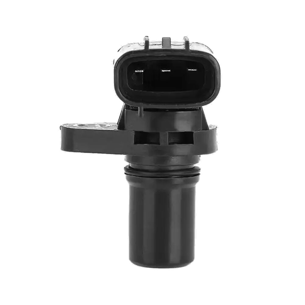
Connector and Terminal Integrity
The electrical connector represents a critical vulnerability point in crankshaft sensor durability, as this interface must maintain reliable contact while resisting vibration, thermal cycling, and environmental contamination. High-quality sensors employ sealed connector designs with multiple weatherproofing features including silicone gaskets, positive locking mechanisms, and gold-plated terminals. The terminal pins should utilize spring-loaded contacts that maintain pressure despite thermal expansion and contraction cycles that can loosen friction-fit connections over time.
Examine the connector retention system carefully when selecting a durable crankshaft sensor, as vibration-induced disconnection ranks among the most common field failure modes. Connectors should incorporate secondary locking tabs or clips that prevent accidental disengagement even when subjected to sustained vibration or when maintenance activities disturb adjacent components. The wire termination method within the connector also affects long-term reliability, with crimped and sealed terminations outperforming soldered connections in high-vibration environments. Premium crankshaft sensors often specify connector designs that meet or exceed automotive industry standards for ingress protection, typically rated IP67 or higher to ensure reliable operation even when submerged temporarily during water crossings or pressure washing.
Internal Component Quality
The internal components of a crankshaft sensor including magnets, coils, semiconductor chips, and circuit boards must meet stringent quality standards to ensure reliable operation throughout the expected service life. Permanent magnets should utilize rare-earth materials such as neodymium-iron-boron alloys that maintain magnetic field strength even after prolonged exposure to elevated temperatures. The coil winding quality affects both signal generation capability and resistance to vibration-induced wire breakage, with precision-wound coils using appropriate wire gauge and insulation materials demonstrating superior longevity.
For Hall effect and optical sensors, the quality of semiconductor components and integrated circuits directly determines reliability under thermal stress and voltage variations. Select sensors that specify automotive-grade electronics with extended temperature ratings rather than commercial-grade components designed for benign operating conditions. The circuit board substrate material and copper trace thickness influence resistance to thermal cycling fatigue, with multilayer boards using high-temperature laminates providing optimal durability. Premium crankshaft sensors undergo conformal coating processes that encapsulate electronic components in protective polymer layers, preventing corrosion from moisture exposure and providing mechanical support that reduces stress on solder joints during vibration.
Environmental Resistance and Operating Conditions
Temperature Performance Range
The temperature performance characteristics of a crankshaft sensor fundamentally determine its suitability for specific applications and operating environments. Engine bay temperatures routinely exceed one hundred degrees Celsius near exhaust components, while cold-start conditions in northern climates can expose sensors to temperatures below negative forty degrees Celsius. A durable crankshaft sensor must maintain accurate signal generation and electronic functionality across this extreme temperature span without calibration drift or component degradation. When evaluating temperature specifications, verify that the stated operating range encompasses both ambient extremes and localized heat sources near the sensor mounting location.
Temperature cycling represents a more severe stress than steady-state exposure, as repeated expansion and contraction induces mechanical stress in housing materials, solder joints, and component interfaces. High-quality crankshaft sensors undergo accelerated thermal cycling testing during development to identify potential failure modes and validate design robustness. The coefficient of thermal expansion for different materials within the sensor assembly must be carefully matched to prevent stress concentration at material interfaces. Sensors intended for heavy-duty applications should specify operational capability after thousands of thermal cycles between temperature extremes, demonstrating resistance to fatigue-induced failure mechanisms.
Vibration and Shock Resistance
Crankshaft sensors mount directly to the engine block and experience continuous vibration throughout operation, with frequency content ranging from low-frequency engine firing pulses to high-frequency combustion noise. This sustained vibration exposure tests every mechanical interface within the sensor assembly, from housing mounting threads to internal component attachments. Durable sensors incorporate vibration isolation features such as elastomeric mounting grommets or flexible lead strain relief that prevents vibration energy from directly coupling into sensitive internal components. The sensor housing design should distribute mounting loads to prevent stress concentration that could lead to crack initiation.
Shock resistance becomes critical in mobile applications where road impacts, potholes, and operational jolts transmit high-acceleration forces through the vehicle structure. Quality crankshaft sensors undergo standardized shock testing that simulates drop impacts and collision-level acceleration events to verify structural integrity. The internal component mounting method significantly affects shock survival, with potted assemblies where components are encapsulated in rigid or flexible compounds demonstrating superior resistance compared to air-gap designs. When selecting sensors for severe-duty applications including off-highway equipment, motorsports, or military vehicles, prioritize units specifically tested and rated for enhanced vibration and shock exposure beyond standard automotive requirements.
Contamination Resistance
The engine bay environment exposes crankshaft sensors to various contaminants including engine oil, transmission fluid, coolant, road salt, and airborne particles. While the sensing tip must maintain a precise air gap to the reluctor wheel, the housing and connector must resist degradation from chemical exposure and physical contamination. High-quality sensors utilize materials and seal designs that prevent oil wicking along the wire bundle into the connector cavity, as this failure mode can cause intermittent electrical faults and corrosion of terminal contacts. The sensing face should incorporate materials resistant to carbon buildup and metallic particle accumulation that could alter the magnetic field or optical path.
Water intrusion represents another significant durability challenge, particularly for vehicles operating in wet conditions or subjected to pressure washing. Durable crankshaft sensors incorporate multiple sealing barriers including o-rings at the housing-to-block interface, gaskets at the connector mating plane, and sealed wire exit points. The seal material selection must balance compression set resistance for long-term sealing effectiveness against chemical compatibility with automotive fluids. Premium sensors undergo water immersion testing and salt spray exposure to validate corrosion resistance and seal integrity. For marine applications or vehicles regularly exposed to saltwater, specify sensors with enhanced corrosion protection including conformal coatings on electronic assemblies and stainless steel hardware.
Compatibility and Installation Considerations
Reluctor Wheel Matching Requirements
The crankshaft sensor must precisely match the reluctor wheel configuration installed on the engine crankshaft, as tooth count, spacing pattern, and missing tooth positions directly affect the engine control unit's ability to calculate crankshaft position and speed. Different engine families utilize various reluctor patterns ranging from simple thirty-six-minus-one configurations to complex multi-pattern wheels encoding both crankshaft and camshaft position information. When selecting a replacement crankshaft sensor, verify complete compatibility with the specific reluctor wheel design, as sensors optimized for different tooth spacing or detection methods may produce unreliable signals or fail to function entirely.
The air gap specification between the crankshaft sensor tip and reluctor wheel teeth critically affects signal amplitude and reliability. Magnetic sensors typically require air gaps between zero point five and two point zero millimeters, with tighter tolerances yielding stronger signals but increasing vulnerability to contact damage if engine movement or mounting hardware wear allows deflection. Hall effect sensors generally tolerate wider air gap variations, but optimal performance still requires adherence to manufacturer specifications. During installation, use proper gap-setting procedures whether involving shim selection, adjustable mounting brackets, or self-setting designs where spring loading establishes correct spacing. A durable sensor installation must maintain the specified air gap despite engine vibration, thermal expansion, and long-term bearing wear.
Electrical Interface Compatibility
The electrical output characteristics of the crankshaft sensor must match the input requirements of the engine control unit to ensure proper signal interpretation. Magnetic inductive sensors produce variable amplitude AC signals that require compatible signal conditioning circuitry, while Hall effect sensors output digital signals with specific voltage levels and current drive capabilities. Mismatched electrical interfaces can result in signal clipping, insufficient trigger threshold voltage, or loading effects that distort waveform characteristics. When replacing a crankshaft sensor, confirm that the new unit maintains identical electrical specifications including output impedance, signal amplitude range, and timing characteristics.
The wiring harness and connector configuration must also match between the replacement sensor and vehicle installation. While physical connector compatibility is obvious, verify that pin assignments remain consistent to prevent reversed polarity or incorrect ground connections that could damage electronic components. Some crankshaft sensors incorporate internal resistors or capacitors that affect signal characteristics, and these passive components must match original specifications to maintain system calibration. For aftermarket sensor selection, prioritize manufacturers who provide detailed electrical specifications and explicitly confirm compatibility with specific engine control unit models rather than generic fitment claims.
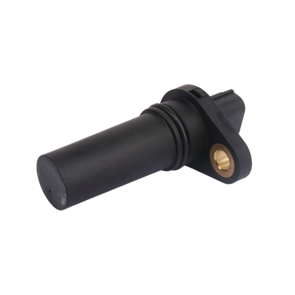
Mounting Hardware and Installation Quality
The mounting method and hardware quality significantly influence crankshaft sensor durability by affecting vibration isolation, thermal expansion accommodation, and resistance to loosening. Thread-in sensors require proper torque application to achieve adequate clamping force without overstressing the housing material or damaging threads in the aluminum engine block. Under-torqued sensors can vibrate loose or allow moisture intrusion past the mounting seal, while over-torqued installations risk cracking the sensor housing or stripping block threads. Always follow manufacturer torque specifications and use calibrated tools rather than estimating tightness by feel.
Bracket-mounted crankshaft sensors depend on secure attachment hardware that resists vibration-induced loosening throughout the service interval. Use thread-locking compounds on mounting bolts unless explicitly prohibited by installation instructions, and verify that all washers and spacers are installed as specified to maintain proper sensor positioning. The routing and securing of the sensor wire harness affects durability by preventing chafing against sharp edges, contact with hot exhaust components, and excessive tension that could fatigue wire strands or pull on the sensor connector. Use proper wire ties or clips at recommended intervals, allowing sufficient slack for thermal expansion and engine movement while preventing wire bundle motion that accelerates insulation wear.
Performance Validation and Quality Assurance
Manufacturing Quality Certifications
The manufacturing quality standards and certifications held by the crankshaft sensor producer provide insight into process control rigor and reliability commitment. Sensors manufactured in facilities certified to ISO 9001 quality management standards demonstrate systematic approaches to process control, traceability, and continuous improvement. For automotive applications, prioritize sensors from manufacturers holding IATF 16949 certification, the automotive industry-specific quality standard requiring additional controls for production part approval processes, change management, and supplier quality assurance. These certifications indicate established procedures for handling non-conformances and implementing corrective actions when quality issues arise.
Environmental management certifications such as ISO 14001 suggest manufacturer commitment to eliminating hazardous materials and following proper disposal procedures that often correlate with general quality consciousness. For applications in regulated industries or where end-of-life recycling is important, verify that the crankshaft sensor complies with restrictions on hazardous substances including lead, mercury, cadmium, and hexavalent chromium. Premium sensor manufacturers often voluntarily exceed minimum regulatory requirements, using environmentally preferable materials and processes that typically also enhance product durability and performance reliability.
Testing and Validation Protocols
Comprehensive testing and validation during product development separates durable crankshaft sensors from marginal designs that may function initially but fail prematurely under service conditions. Reputable manufacturers conduct extensive environmental testing including temperature cycling, thermal shock, humidity exposure, salt spray corrosion, and vibration endurance protocols that simulate accelerated lifetime exposure. Request documentation of testing procedures and acceptance criteria when evaluating sensor options, as specific test parameters and duration directly indicate expected field reliability. Sensors validated through thousands of hours of engine dynamometer testing demonstrate proven performance under realistic operating conditions.
Electrical performance validation should encompass signal quality measurements across the full operating temperature range and engine speed spectrum. Quality sensors maintain consistent signal amplitude, rise time, and timing accuracy despite environmental extremes. Electromagnetic compatibility testing verifies that the sensor operates reliably in the presence of radio frequency interference from ignition systems, alternators, and electronic accessories while not generating emissions that could interfere with other vehicle systems. For critical applications, seek sensors that have completed full vehicle integration testing and field validation in representative duty cycles rather than laboratory testing alone.
Warranty Coverage and Field Performance Data
The warranty terms offered by the crankshaft sensor manufacturer reflect confidence in product durability and provide financial protection against premature failure. Extended warranty periods ranging from three to five years or mileage-based coverage exceeding one hundred thousand kilometers indicate manufacturer commitment to quality and expected longevity. Review warranty conditions carefully to understand coverage limitations, required installation procedures, and claim documentation requirements. Some manufacturers offer prorated warranty coverage or free replacement programs for verified quality-related failures, demonstrating accountability for product performance.
Field performance data from fleet operators, warranty claim databases, and professional technician feedback provides valuable real-world validation of crankshaft sensor durability. Sensors with documented low failure rates in high-mileage applications or severe-duty environments demonstrate proven reliability beyond manufacturer claims. Professional automotive forums and technical service bulletins often identify problematic sensor designs or common failure modes that may not be apparent from product specifications alone. When possible, consult with technicians experienced in your specific application to identify sensor brands and part numbers with established reputations for durability versus those known for premature failures or chronic problems.
FAQ
How often should a crankshaft sensor be replaced as preventive maintenance?
Crankshaft sensors do not typically require scheduled replacement as preventive maintenance when a quality unit is properly installed and functioning correctly. Most automotive manufacturers do not specify replacement intervals for crankshaft sensors, expecting them to last the vehicle lifetime under normal operating conditions. However, in severe-duty applications including high-mileage commercial vehicles, motorsports, or extreme environmental exposure, some operators replace crankshaft sensors proactively at major service intervals such as every two hundred thousand kilometers or five years to avoid unexpected failures. Monitoring sensor signal quality during routine diagnostics provides better indication of replacement need than arbitrary time or mileage intervals.
Can a crankshaft sensor be cleaned and reinstalled if contaminated?
Surface contamination on the crankshaft sensor tip from oil residue or metallic particles can sometimes be carefully cleaned using appropriate solvents and non-abrasive materials without damaging the sensor. However, if contamination has entered the sensor housing through failed seals or if the sensing element shows corrosion or physical damage, cleaning will not restore proper function and replacement is necessary. The air gap specification must be verified after any reinstallation, as improper gap settings cause unreliable operation regardless of sensor cleanliness. Generally, given the relatively low cost of quality sensors compared to diagnosis and labor time, replacement rather than cleaning represents the more reliable approach when contamination or performance issues are detected.
What causes most crankshaft sensor failures in automotive applications?
The most common causes of crankshaft sensor failure include heat exposure beyond design limits from proximity to exhaust components or inadequate heat shielding, vibration fatigue of internal connections or solder joints, water intrusion through failed seals leading to corrosion, and mechanical damage from improper installation or contact with rotating components. Oil contamination of connectors causes intermittent electrical faults that may initially appear as sensor failures but actually result from poor connection quality. Physical damage during maintenance activities when technicians inadvertently strike sensors with tools or when engine work requires sensor removal also accounts for significant failure rates. Selecting sensors with robust construction and following proper installation procedures minimizes these common failure modes.
Are aftermarket crankshaft sensors as reliable as original equipment parts?
Aftermarket crankshaft sensor quality varies considerably depending on the manufacturer, with premium aftermarket brands often matching or exceeding original equipment specifications while economy alternatives may compromise materials or quality control to achieve lower pricing. Reputable aftermarket sensor manufacturers utilize the same design principles and similar component quality as original equipment suppliers, sometimes producing sensors in the same factories under different brand labels. The key distinction lies in validation testing rigor and manufacturing consistency rather than inherent design limitations. When selecting aftermarket sensors, prioritize brands with established reputations, comprehensive warranties, and specific compatibility confirmations for your application rather than choosing based solely on lowest price, as sensor replacement labor costs typically dwarf the price difference between economy and premium parts.