
The throttle position sensor is one of the most critical input devices in a modern fuel-injected engine management system. Whether installed on a motorcycle, passenger car, or light commercial vehicle, this small but highly precise component continuously monitors the angular position of the throttle valve and transmits that data to the engine control unit. Without accurate throttle position data, the ECU cannot calculate the correct fuel injection quantity, ignition timing, or idle stabilization response. Understanding how this sensor works and why it matters is essential for engineers, technicians, and procurement professionals working in the automotive and powersports industries.
In fuel injection systems, the throttle position sensor serves as the primary signal source for driver intent. When a rider or driver opens the throttle, the sensor immediately converts that mechanical movement into an electrical signal that the ECU interprets in real time. This closed-loop feedback mechanism allows the engine to respond with precision, delivering the right air-fuel mixture at every load point. As emission standards tighten and engine calibration becomes more sophisticated, the role of the throttle position sensor has grown from a simple feedback device into a foundational element of engine performance and compliance.
Working Principle of the Throttle Position Sensor
Mechanical-to-Electrical Signal Conversion
The throttle position sensor operates on the principle of converting rotational mechanical movement into a proportional electrical output. The sensor is mounted directly on the throttle body shaft, so any rotation of the throttle plate causes a corresponding change in the sensor's internal resistance or voltage output. This direct mechanical coupling ensures that the electrical signal accurately reflects the real-time position of the throttle valve at all times.
In the most common resistive type, the throttle position sensor uses a potentiometer design. A wiper contact moves along a resistive track as the throttle shaft rotates, and the voltage at the wiper changes linearly with the angle of rotation. The ECU reads this voltage, typically ranging from around 0.5 volts at idle to approximately 4.5 volts at wide-open throttle, and maps it to a precise throttle opening percentage.
More advanced designs use non-contact Hall-effect technology, where a magnetic field variation replaces the physical wiper contact. This eliminates mechanical wear on the resistive track, extending the operational lifespan of the throttle position sensor significantly. Hall-effect sensors are increasingly preferred in high-cycle applications such as motorcycles and performance vehicles where throttle actuation frequency is very high.
Signal Processing and ECU Integration
Once the throttle position sensor generates its output voltage, the signal travels through the vehicle's wiring harness to the ECU's analog-to-digital converter. The ECU samples this signal at high frequency, often hundreds of times per second, to track not just the absolute throttle position but also the rate of change. A rapid increase in throttle angle signals an acceleration demand, prompting the ECU to enrich the fuel mixture and advance ignition timing accordingly.
The throttle position sensor signal is also cross-referenced with other sensor inputs, including the manifold absolute pressure sensor, crankshaft position sensor, and oxygen sensor. This multi-input logic allows the ECU to validate the throttle position reading and detect anomalies. If the throttle position sensor output falls outside its expected range or contradicts other sensor data, the ECU triggers a diagnostic fault code and may activate a limp-home mode to protect the engine.
Modern dual-track throttle position sensor designs provide two independent output signals simultaneously. The ECU compares both signals in real time, and if they diverge beyond a calibrated threshold, the system flags a fault. This redundancy is especially important in ride-by-wire systems where there is no direct mechanical link between the throttle grip and the throttle valve, making sensor reliability a safety-critical requirement.
Main Advantages of the Throttle Position Sensor
Precise Fuel Injection Control
One of the most significant advantages of the throttle position sensor is its direct contribution to fuel injection accuracy. By providing the ECU with a continuous, real-time signal of throttle valve angle, the sensor enables precise calculation of the air mass entering the engine at any given moment. This allows the fuel injector pulse width to be calibrated with a level of accuracy that carburetor-based systems simply cannot achieve.
In practical terms, this means the engine receives the correct stoichiometric air-fuel ratio across the entire operating range, from cold start and idle through partial load and full acceleration. The throttle position sensor is particularly important during transient conditions, such as sudden throttle opening or closing, where fuel delivery must respond within milliseconds to prevent hesitation, stumbling, or over-fueling.
For motorcycle applications like the Bajaj Pulsar N250 and N160 Fi, where engine displacement is moderate and throttle response is a key performance attribute, the throttle position sensor plays a central role in delivering the crisp, linear power delivery that riders expect. Any degradation in sensor accuracy directly translates into noticeable drivability issues.
Emission Reduction and Regulatory Compliance
The throttle position sensor is a key enabler of modern emission control strategies. Accurate throttle position data allows the ECU to maintain tight control over the air-fuel ratio, keeping combustion within the narrow window required for the catalytic converter to operate at peak efficiency. Without reliable throttle position feedback, the engine would frequently run rich or lean, producing excess hydrocarbons, carbon monoxide, or nitrogen oxides.
As emission regulations in markets across Asia, Europe, and the Americas continue to tighten, the precision of the throttle position sensor becomes increasingly important for homologation. Manufacturers calibrating engines to meet BS6, Euro 5, or equivalent standards rely on the throttle position sensor as a foundational input for their emission management strategies. A faulty or out-of-specification throttle position sensor can cause a vehicle to fail emission testing even if all other components are functioning correctly.
The sensor also supports exhaust gas recirculation control and idle speed management, both of which are directly tied to emission performance. By accurately reporting throttle position during deceleration and idle, the throttle position sensor helps the ECU cut fuel delivery at the right moments, reducing unburned fuel emissions during engine braking and coasting phases.
Enhanced Engine Diagnostics and Fault Detection
Another major advantage of the throttle position sensor is its role in the vehicle's onboard diagnostic system. Because the sensor output is continuously monitored by the ECU, any deviation from expected values is immediately detectable. This allows technicians to identify throttle-related faults quickly and accurately using standard OBD diagnostic tools, reducing diagnostic time and repair costs.
Common fault codes associated with the throttle position sensor, such as P0120 through P0124 in the OBD-II standard, provide specific information about whether the fault is a signal range issue, a circuit malfunction, or a correlation error between dual-track outputs. This level of diagnostic granularity is only possible because the throttle position sensor provides a well-defined, continuously validated electrical signal.
For fleet operators and service workshops, the diagnostic capability of the throttle position sensor translates into lower downtime and more predictable maintenance schedules. Sensors that are approaching end-of-life often show gradual signal degradation before complete failure, giving technicians an opportunity to replace the throttle position sensor proactively rather than reactively.
Throttle Position Sensor in Motorcycle Applications
Design Considerations for Two-Wheeler Engines
Motorcycle engines present unique challenges for throttle position sensor design. The sensor must withstand high vibration levels, wide temperature swings, and exposure to moisture and road contaminants, all while maintaining signal accuracy over tens of millions of throttle cycles. For commuter and sport motorcycles in emerging markets, durability and cost-effectiveness are equally important design criteria.
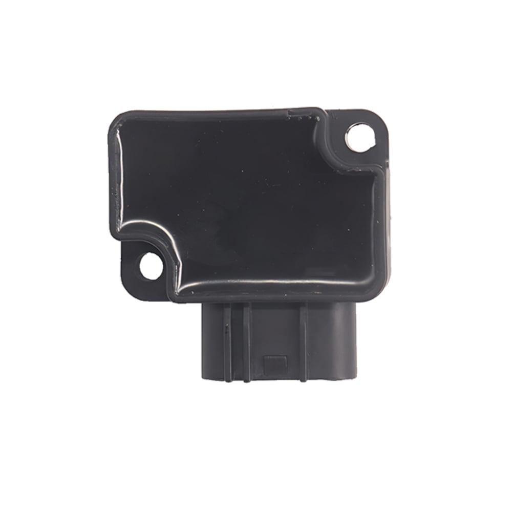
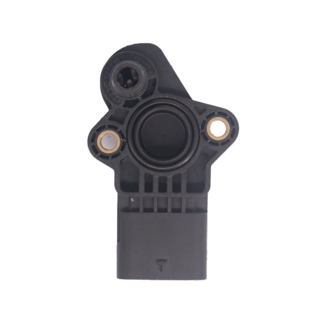
The throttle position sensor used on fuel-injected motorcycles like the Bajaj Pulsar series is typically a compact, sealed unit designed to mount directly on the throttle body. The connector and sealing must meet IP67 or equivalent ingress protection standards to prevent moisture intrusion, which is a common cause of signal drift and premature sensor failure in real-world riding conditions.
Calibration is another critical factor. The throttle position sensor must be precisely matched to the throttle body geometry and the ECU's voltage mapping table. An incorrectly calibrated or mismatched throttle position sensor can cause idle instability, poor throttle response, or incorrect fuel trim corrections, all of which degrade the riding experience and can trigger false fault codes.
Replacement and Compatibility Factors
When replacing a throttle position sensor on a motorcycle, compatibility with the original equipment specification is essential. The replacement sensor must match the original in terms of connector pinout, voltage output range, mechanical mounting dimensions, and shaft coupling geometry. Using an incompatible throttle position sensor, even one that physically fits, can result in incorrect ECU calibration and persistent fault codes.
For models like the Bajaj Pulsar N250 and N160 Fi, sourcing a throttle position sensor that is specifically engineered for the original throttle body ensures that the ECU's fuel and ignition maps remain valid without requiring recalibration. This is particularly important in markets where dealer-level ECU reprogramming tools may not be readily available.
Quality control in manufacturing is a key differentiator among throttle position sensor suppliers. Sensors produced with tight resistance tolerance, consistent wiper contact pressure, and robust connector materials will maintain accurate output over a longer service life. Procurement teams evaluating throttle position sensor suppliers should request detailed specifications including output linearity, operating temperature range, and cycle life test data.
Factors That Affect Throttle Position Sensor Performance
Wear, Contamination, and Signal Drift
In potentiometer-type designs, the resistive track and wiper contact are subject to mechanical wear over time. As the contact surface degrades, the throttle position sensor may develop dead spots, areas where the output voltage does not change smoothly with throttle movement. These dead spots cause the ECU to receive erratic or missing position data, leading to hesitation, rough idle, or sudden power loss.
Contamination from oil vapor, fuel residue, or moisture ingress can also affect the internal resistance of the throttle position sensor, causing the output voltage to shift away from its calibrated baseline. This type of signal drift is particularly insidious because it may not trigger a fault code immediately, instead causing subtle drivability issues that are difficult to diagnose without measuring the sensor output directly with a multimeter or oscilloscope.
Regular inspection of the throttle position sensor connector and wiring harness is good maintenance practice, especially in high-mileage vehicles or those operating in harsh environments. Corroded connector pins are a common source of intermittent throttle position sensor faults and can often be resolved with proper cleaning and connector sealing without replacing the sensor itself.
Installation Quality and Calibration Accuracy
The accuracy of a throttle position sensor is only as good as its installation. If the sensor is not correctly aligned with the throttle shaft, the mechanical coupling will introduce angular error into the output signal. Even a small misalignment can shift the idle voltage reading outside the ECU's expected range, causing idle hunting or incorrect fuel trim corrections at low load.
After installation, some throttle position sensor designs require a calibration or adaptation procedure using a diagnostic tool. This procedure teaches the ECU the exact voltage values corresponding to the closed throttle and wide-open throttle positions for the newly installed sensor. Skipping this step can result in the ECU operating with incorrect reference points, degrading fuel injection accuracy across the entire throttle range.
Technicians should always verify the throttle position sensor output voltage at idle and at wide-open throttle after installation, comparing the readings against the manufacturer's specification. This simple verification step catches installation errors before they cause drivability complaints or emission test failures, saving time and cost for both the workshop and the vehicle owner.
FAQ
What are the symptoms of a failing throttle position sensor?
Common symptoms include rough or unstable idle, hesitation during acceleration, sudden surging or loss of power, poor fuel economy, and illumination of the check engine light. In severe cases, the engine may enter limp-home mode, restricting power output to protect the drivetrain. These symptoms can overlap with other sensor faults, so confirming the issue with a diagnostic scan tool is recommended before replacing the throttle position sensor.
Can a throttle position sensor be cleaned instead of replaced?
In some cases, cleaning the throttle position sensor connector and ensuring a secure, corrosion-free electrical connection can resolve intermittent signal faults. However, if the sensor's internal resistive track is worn or the output voltage is outside specification, cleaning will not restore accuracy. A throttle position sensor showing dead spots, non-linear output, or voltage readings outside the manufacturer's range should be replaced rather than cleaned.
How does the throttle position sensor differ from a throttle body position sensor in ride-by-wire systems?
In traditional cable-actuated systems, a single throttle position sensor monitors the throttle valve directly. In ride-by-wire systems, there are typically two sensor sets: one on the throttle grip or pedal to detect driver input, and one on the throttle body to confirm actual valve position. Both sets use throttle position sensor technology, but the ECU compares their outputs to verify that the throttle valve is responding correctly to the driver's command, adding a layer of safety redundancy.
How often should a throttle position sensor be replaced?
There is no fixed replacement interval for a throttle position sensor under normal operating conditions. Most sensors are designed to last the service life of the vehicle if the electrical connections remain clean and the sensor is not subjected to physical damage. Replacement is typically condition-based, triggered by diagnostic fault codes, confirmed out-of-range output readings, or drivability symptoms that have been traced to the throttle position sensor through systematic diagnosis.